As opposed to autonomous Wireless Access Points (WAP), the lightweight, controller-based Wireless System brings much more benefits than the traditional standalone APs. In this session, we’ll briefly explain the benefits of a controller based wireless system and illustrate a typical wireless system design in a corporate environment. An in-depth, step-by-step tutorial on Cisco Wireless Controller Configuration (WLC) is followed. At the end of the session, I will also make recommendations on the equipment that you may want to consider.
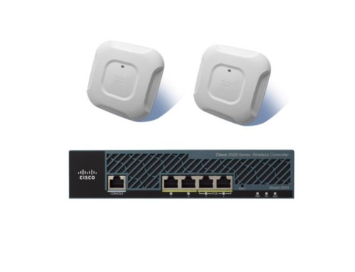
Our configuration example is based on the highly popular Cisco Mobility Express Bundle , running on code 8.1.111.0. The bundle comes with a Cisco 2504 Wireless Controller and two Access Points. Depending the AP models, the bundle is priced between $1500 and $3500 USD. The default license comes with the Controller supports up to 25 APs and you may upgrade the license to 75 APs with code 7.4 and later. It is a great deal for any small to medium sized business to set up their wireless infrastructure. It is robust, reliable and scalable.
Controller-based Wireless System benefits
- Centralized Management, all configuration, code upgrade are managed at the controller level.
- Easy to deploy APs, configurations are pushed to APs as they come online.
- Hierarchical design makes it scalable: Each controller can manage hundreds of APs. Multiple controllers report to a centralized management system called Cisco Prim Infrastructure. Many people still use Network Control System (NCS) and Wireless Control System (WCS).
- Radio Resource Management (RRM): allows the controller to dynamically control power and channel assignment of APs. Cisco Unified WLAN Architecture continuously analyzes the existing RF environment, automatically adjusting the AP power levels and channel configurations to mitigate channel interference and signal coverage problems. (pretty cool!)
- Mobility and roaming: all the APs within the same mobility group share the same configuration. As long as there is no coverage gap, wireless clients can roam among different APs without losing a ping. This feature enables employs moving between branch offices without changing their wireless configurations.
- Self-Healing Mechanism: When an AP radio fails, the controller detects the change and manages its nearby APs to increase their radio power to cover the hole.
- Client location tracking: If you deployed a cisco Wireless Location Appliance in your system, you may import the building layout and pinpoint where a mobile user is located and which AP he/she is on.
Cisco Wireless Controller Configuration Example
Wireless Network Design
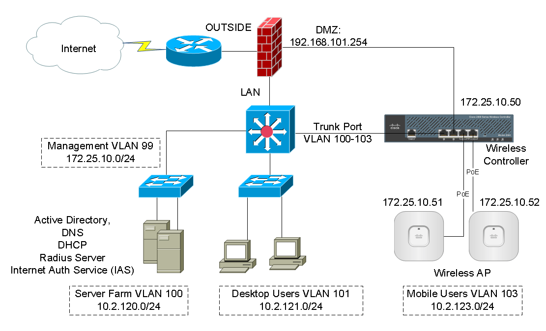
In a typical corporate environment, network consists of multiple VLANs and security layers. For simplicity, the sample network consists of 4 VLANs and 3 security zones.
VLAN 99 = management network
VLAN 100 = server network
VLAN 101 = desktop user network
VLAN 103 = wireless user network
Firewall outside = Internet
Firewall inside = LAN
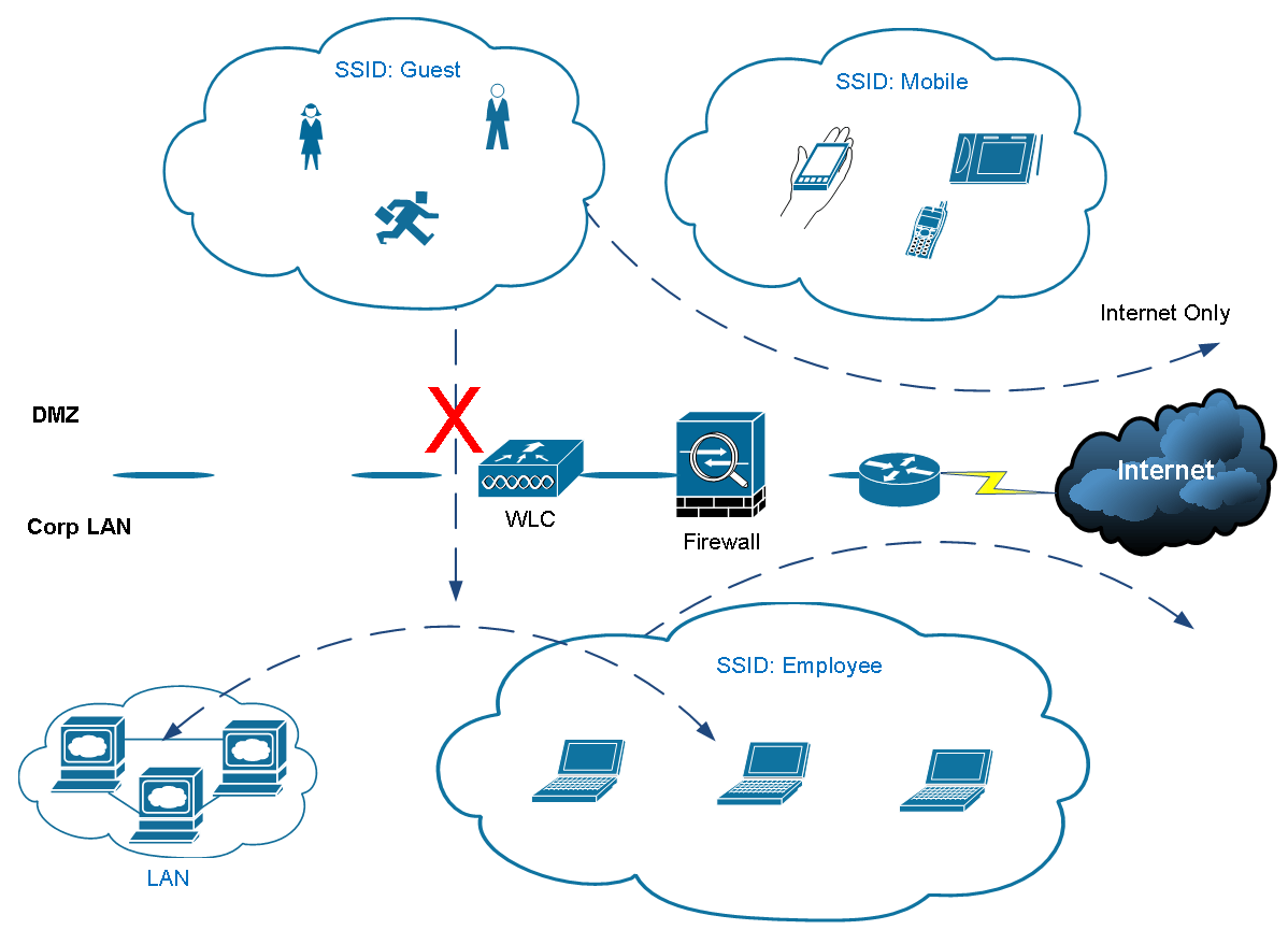
Firewall DMZ = guest wi-fi (no access to the LAN, Internet only.)
IP assignment for the wireless infrastructure
- Wireless Controller Interfaces:
- management: 172.25.10.50
- ap-manager: 172.25.10.50
- virtual: 1.1.1.1
- AP01: 172.25.10.52
- AP02: 172.25.10.53
SSID:
- Employee: VLAN103 – 10.2.123.2 /24
- Guest: 192.168.202.30 /24
You’ll need to prepare your servers and network to work with the wireless system:
- Microsoft Active Directory and DNS
- DHCP Server with new scope configured
- IP helper-address configured on the switch
- Microsoft Radius (IAS) Server
- Microsoft Enterprise root CA (optional)
- Separate DMZ for wireless infrastructure
The logical traffic flow is shown.
You can download and import our working configuration described in this document.
As part of our documentation effort, we maintain current and accurate information we provided. Documentations are routinely reviewed and updated. We ask for your email address to keep you notified when the article is updated.
Cisco Wireless Controller Configuration
Initial Setup for Wireless Controller
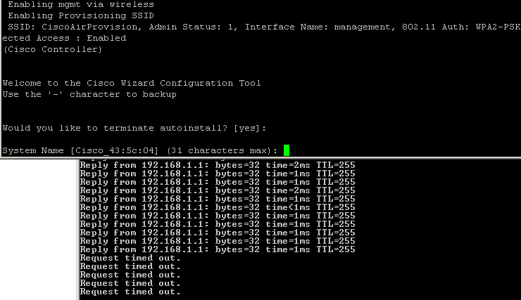
The product comes with a “Quick Start Guide”. If you tried to follow the direction on the Guide and setup the Controller you’ll quickly discover that it does not work. It asks you to connect a laptop to Port#2 and power up the Controller. Assign an IP from 192.168.1.x range on you laptop and access the Controller’s web console at http://192.168.1.1. In my case I found that website is not accessible after the Controller has booted up. I could not even ping the IP 192.168.1.1 from a laptop. The IP was pingable at one point during the boot process but eventually stopped.
After researching, I realized that the Controller needs to be first setup using CLI over a console cable. The Controller is connected to a console cable and powered on, the boot sequence showed starting all the services. When tried to terminate the Auto-install script after pressing the Enter key, the console screen was frozen and would not accept any key input. Pinging and web browsing to 192.168.1.1 both timed out. I also tried from a different computer, tried factory reset on the Controller, same behavior. First thought it was a bad hardware.
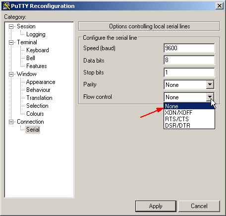
After contacting Cisco support, the solution is “set flow-control to none” on your console client such as Putty and SecureCRT. I’ve been using the default console settings (with flow-control on) for many years and configured all kinds of Cisco product. I never had any issue. Ask why Cisco made their Wireless Controller special? Here is the setting you must use:
9600 baud
8 data bits
No flow control
1 stop bit
No parity
Now we can go through the initial setup wizard over console. Most questions are self-explanatory.
Welcome to the Cisco Wizard Configuration Tool
Use the '-' character to backup

Would you like to terminate autoinstall? [yes]:

System Name [Cisco_43:5c:04] (31 characters max): CORPWLC
Enter Administrative User Name (24 characters max): admin
Enter Administrative Password (3 to 24 characters): *********
Re-enter Administrative Password                 : *********

Enable Link Aggregation (LAG) [yes][NO]: no

Management Interface IP Address: 172.25.10.50
Management Interface Netmask: 255.255.255.0
Management Interface Default Router: 172.25.10.1
Cleaning up Provisioning SSID
Management Interface VLAN Identifier (0 = untagged):
Management Interface Port Num [1 to 4]: 1
Management Interface DHCP Server IP Address:
Invalid response

Management Interface DHCP Server IP Address: 172.25.10.1

Virtual Gateway IP Address: 1.1.1.1

Multicast IP Address:
Invalid response

Multicast IP Address: 239.255.1.60

Mobility/RF Group Name: CORP

Network Name (SSID): Employee

Configure DHCP Bridging Mode [yes][NO]: yes
Warning! Enabling Bridging mode will disable Internal DHCP server and DHCP Proxy feature.
May require DHCP helper functionality on external switches.

Allow Static IP Addresses [YES][no]: yes

Configure a RADIUS Server now? [YES][no]: no
Warning! The default WLAN security policy requires a RADIUS server.
Please see documentation for more details.

Enter Country Code list (enter 'help' for a list of countries) [US]:

Enable 802.11b Network [YES][no]: no
Enable 802.11a Network [YES][no]: no
Enable Auto-RF [YES][no]: -
Enable 802.11a Network [YES][no]: -

Enable 802.11b Network [YES][no]: yes
Enable 802.11a Network [YES][no]: yes
Enable 802.11g Network [YES][no]: yes
Enable Auto-RF [YES][no]: yes

Configure a NTP server now? [YES][no]: no
Configure the system time now? [YES][no]: yes
Enter the date in MM/DD/YY format: 07/29/2015
Invalid response

Enter the date in MM/DD/YY format: 07/29/15
Enter the time in HH:MM:SS format: 16:49:00

Would you like to configure IPv6 parameters[YES][no]: no

Configuration correct? If yes, system will save it and reset. [yes][NO]: yes
Cleaning up Provisioning SSID

Configuration saved!
Resetting system with new configuration...

Configuration saved!
Resetting system with new configuration...
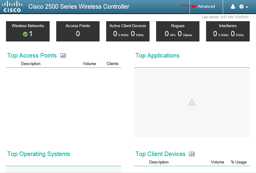
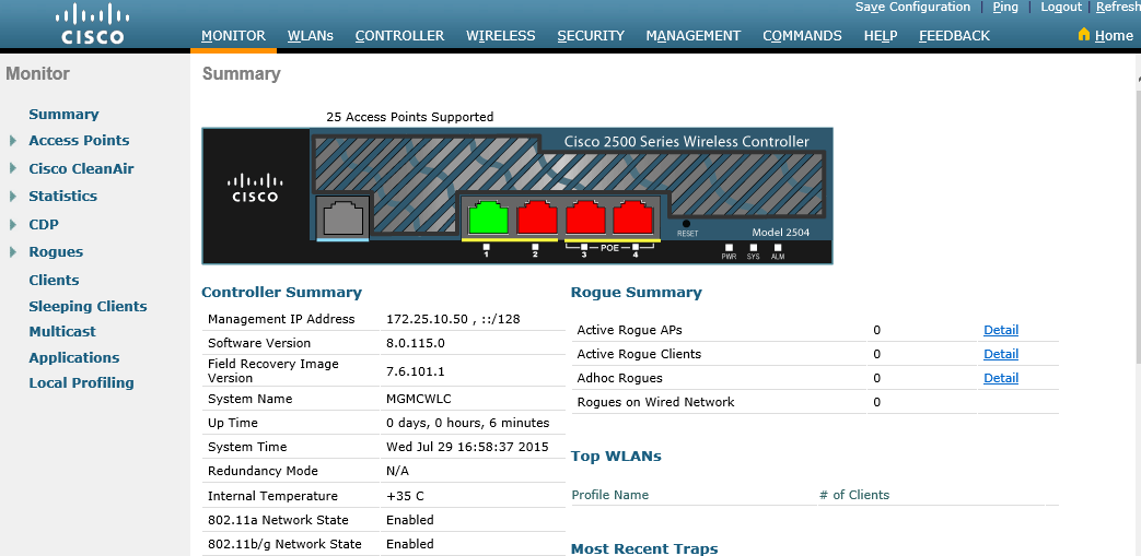
After the Controller has booted up, you can access its web interface at http://IP-address. In our example it is http://172.25.10.50.
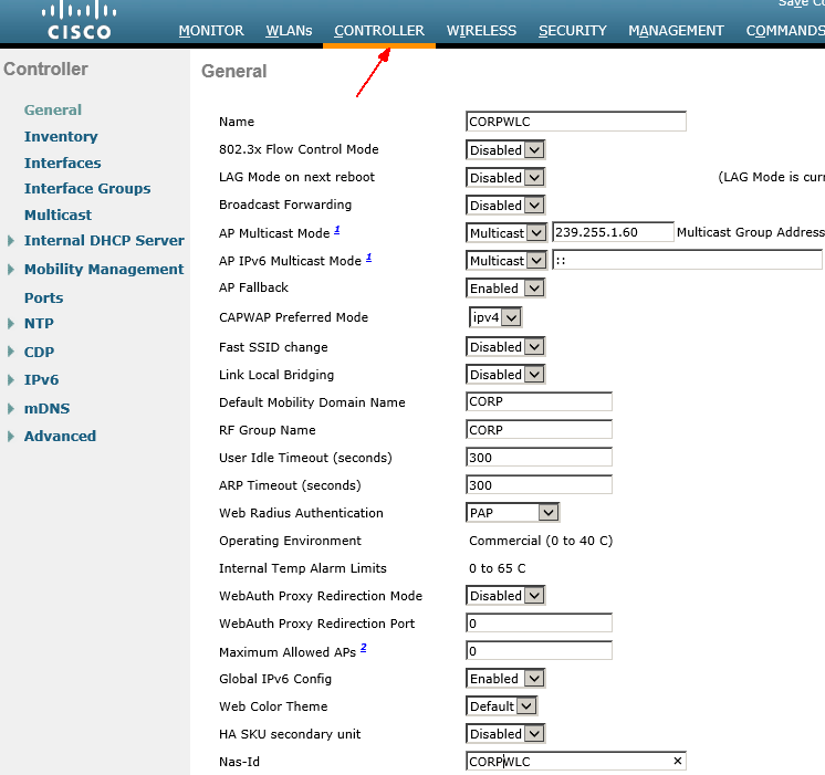
Go to Controller-Interfaces and confirm your management IP and virtual IP are set.
Initial Setup for Wireless Access Points (WAP)
This is the beauty of deploying a controller based system. The configuration on a WAP is minimum. All it needs is a management IP address so that it can reports to the Controller. Once all the WAPs are registered with the Controller, you can forget about them. (do remember behind which ceiling tile the APs are installed. After many years, you may not remember where they are.)
There are two ways of setting up a Wireless Access Point (WAP):
- Use DHCP and the Controller will assign an IP to the WAP
- Use static IP for management
Unless you have hundreds of WAPs needed to be deployed on a large campus, I recommend staging the WAPs and assigning a static IP on each of them. Label with hostname and IP address where you can see without crawling into the ceiling. It’ll make your life a lot easier in the future. There is another reason why I recommend using static IPs for WAP management. Most network administrators do not like enabling DHCP service on the network infrastructure subnet. It makes sense that you want all the network devices to have a statically assigned IP address for easy management, monitoring and documentation purposes.
To get a WAP setup, there are two things you need to do – assign a static IP on the WAP, and tell it where to find the Controller to associate with (if it is not on the same broadcast domain).
Connect the WAP with Console cable, and power. If you purchased a Cisco Mobility Express Bundle, and most Cisco WAPs do not come with a power adapter. They assume you’re going to use PoE. Your Controller normally comes with two PoE ports. You may connect your AP directly to one of the PoE ports on the Controller to power it up.
You are going to see some log messages complaining about unable to get an IP from the DHCP server. It is because we did not configure the Controller to give out IP addresses. We must configure them manually.
*Mar 1 00:01:44.511: %CAPWAP-3-DHCP_RENEW: Could not discover WLC. Either IP address is not assigned or assigned IP is wrong. Renewing DHCP IP.

Not in Bound state.

Enable password is Cisco (upper case “C”).
Configure using the following commands.
AP#capwap ap ip address <IP address> <subnet mask>
AP#capwap ap ip default-gateway <IP-address>
AP#capwap ap controller ip address <IP-address>
AP#capwap ap hostname <name>(optional)
Here is what I configured:
AP84b8.02a4.695c#capwap ap ip address 172.25.10.52 255.255.255.0If the WAP is directly connected to the Controller’s port, an IP is all it needed. If it is on a different subnet than the Controller, you need to configure the gateway and some DNS tricks explained in later session.
As soon as the WAP is configured with an IP, the magic happens. You’ll seem bunch of log messages coming out of the console and the LED turns Blue, Red, Green and flashing. The WAP is now registering with the Controller; the Controller tells it to upgrade its code if it finds code version inconsistency. After about 3 to 5 minutes, the first WAP appears in your Controller’s management console.
Repeat the same process until all your WAPs are registered with the Controller.
Note: If you prefer using DHCP to assign management IPs to the WAP, you need to either configure an Internet DHCP Server on the Controller itself or, pass the DHCP Request to your existing DHCP server on your network. You’ll need to configure “ip address-helper” on your Layer3 switch, as well as setup DNS records to help Wireless LAN Controller Discovery. Read more here:
Lightweight AP (LAP) Registration to a Wireless LAN Controller
Microsoft Windows 2003 DNS Server for Wireless LAN Controller (WLC) Discovery Configuration Example
From this point on, all the configuration is done at the Controller level.
Wireless Infrastructure Configuration
Based on our design example, we are going to configure-
- An Employee SSID for internal users. It has access to all internal subnets.
- A Guest SSID for visitors. It only has Internet access.
- Internal user authentication is through Microsoft Active Directory.
- Guest users are authenticated through webpage. Accounts are created manually on the Controller with automatic expiration. i.e. 8 hrs.
We first need to setup logical “Interfaces” on the Controller. As opposed to physical interfaces, logical interfaces are used for management and communications between AP and Controller, wireless clients with the AP and Controller. Logical interfaces can be assigned to one or more physical interfaces.
Login the wireless Controllers admin console at http://172.25.10.50/. Go to Controller –> Interfaces. You should already have management and virtual interfaces created during the initial setup.
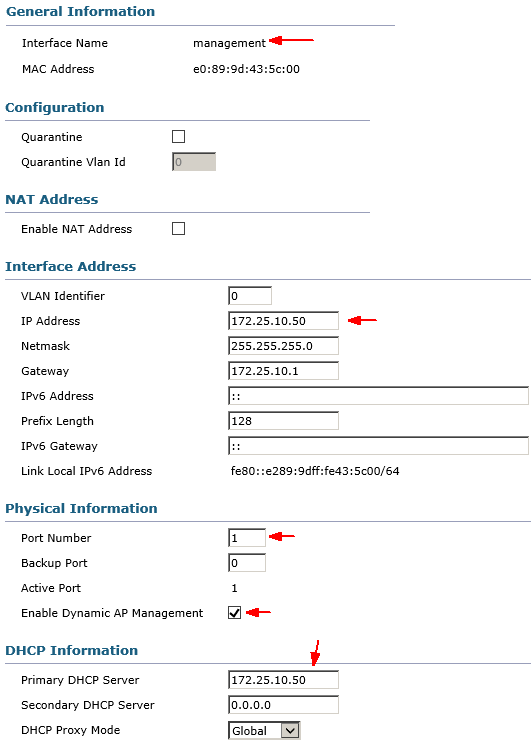
Click on “management” interface and review the settings.
Interface IP address is the IP address you used to connect to the Controller for management. The Controller’s physical port#1 is connected to your switch over trunk port for management traffic. Any DHCP request over this management interface will be redirected to the DHCP servers specified here. Two important concepts you need to understand-
AP-manager – Enable Dynamic AP Management
By default, the management interface and AP-manager are bounded together to port 1. Three more AP-managers can be created on other physical ports (2, 3, and 4) in the same subnet as management interfaces. APs that join the controller are load balanced such that each port on the controller shares the load of the 50 APs. It is recommended to have all AP-managers in the same subnet as a management interface. For brevity, we will use the default AP-manager bundled with “management” interface.
Note: The 2500, 5500, and WiSM2 platforms no longer require a dedicated AP-manager interface to manage APs. It has been combined into the management interface.
DHCP Proxy Mode (Global, Enable, Disable)
First of all, if you use the Controller’s internal DHCP server, the internal DHCP server only works (for wireless clients) with DHCP proxy enabled.
Comparison of Internal DHCP and Bridging Modes
The two main DHCP modes on the controller are either DHCP proxy or DHCP bridging. With DHCP bridging the controller acts more like a DHCP back with autonomous AP’s. A DHCP packet comes into the AP via a client association to a SSID that is linked to a VLAN. Then, the DHCP packet goes out that VLAN. If an IP helper is defined on that VLAN’s layer 3 gateway, the packet is forwarded to that DHCP server via directed unicast. The DHCP server then responds back directly to the layer 3 interface that forwarded that DHCP packet. With DHCP proxy, it is the same idea, but all of the forwarding is done directly at the controller instead of the VLAN’s layer 3 interface. For example, a DHCP request comes in to the WLAN from the client, the WLAN then will either use the DHCP server defined on the VLAN’s interface *or* will use the DHCP override function of the WLAN to forward a unicast DHCP packet to the DHCP server with the DHCP packets GIADDR field filled out to be the VLAN interface’s IP address.
You must enable DHCP proxy on the controller to allow the internal DHCP server to function.
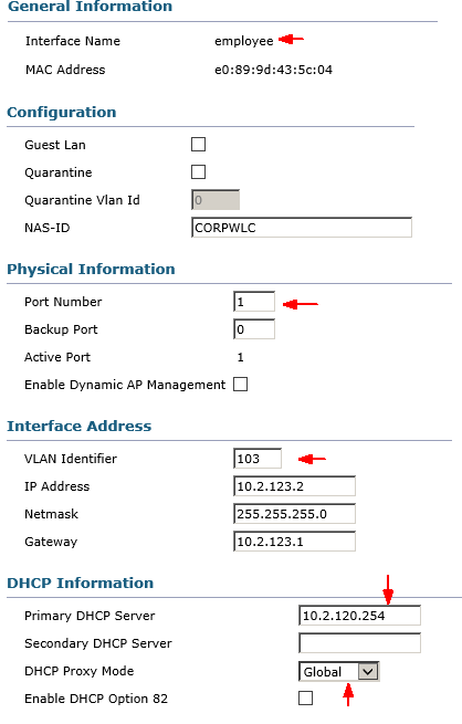
Save the configuration by clicking on Apply. We’ll create a new interface called “employee”. This interface is intended for all internal users to connect to. It has access to the entire LAN.
Keep in mind that if you connected the Controller to your network switch over a trunk port, you need to specify the VLAN Identifier to match the VLAN ID where the subnet resides. In our case it is VLAN 103. Remember we had it set to “0” for “management” interface? The management interface uses the untagged, native VLAN to communicate. Here is an example configuration of the switch trunk port where the Controller is connected.
Management VLAN 99
Data VLAN 100-103
interface GigabitEthernet1/0/10
 description WIFI-WLC1
 switchport trunk native vlan 99
 switchport trunk allowed vlan 99-103
 switchport mode trunk
 spanning-tree guard root
 ip dhcp snooping limit rate 100
end
We planned to use our existing DHCP server (10.2.120.254) to assign IPs to wireless clients. You have DHCP Proxy Mode set to Global, which inherits the global configuration set in Controller -> Advanced -> DHCP. It is disable or bridge mode by default.
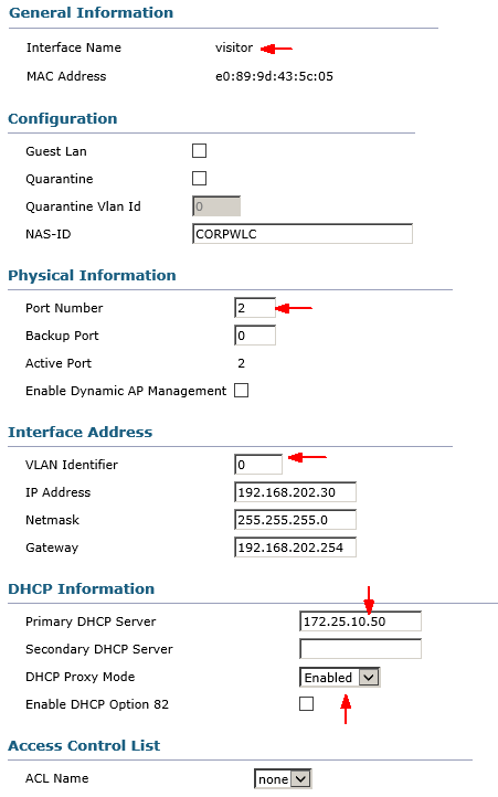
Next, create a visitor interface.
Note I assigned Port Number 2 for visitor’s interface because physical segregation is desired. Port#2 is directly connected to the firewall’s DMZ interface without touching internal LAN.
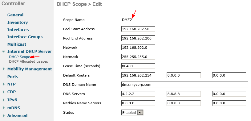
Create an Internet DHCP Scope for Guest users.
We do not allow guests to even use our internal DHCP servers. They’ll get an IP assignment from the Controller itself.
Controller Internal DHCP Server
The internal DHCP server was introduced initially for branch offices where an external DHCP server is not available. It is designed to support a small wireless network with less than ten APs that are on the same subnet. The internal server provides IP addresses to wireless clients, direct-connect APs, appliance-mode APs on the management interface, and DHCP requests that are relayed from APs. It is not a full-blown general purpose DHCP server. It only supports limited functionality and will not scale in a larger deployment.
Configure Wireless Access Points
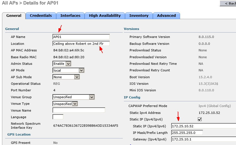
Go to Wireless tab and select All APs. You’ll see the APs associated with the Controller. Configure it by click on the AP Name.
Everything else can stay default value unless you have special requirements. Click on Apply and the AP will reboot. Repeat the same process for all your APs.
Configure RADIUS Server for Internal User Authentication
In an enterprise network, users are commonly managed and authenticated through Microsoft Active Directory. User accounts are centrally managed. Only one set of credential to login to everything. We have created an AD Group Policy so that the Wireless settings are pushed to mobile user profiles. Whenever a user comes to the office with a laptop, it is automatically connected to the “Employee” SSID.
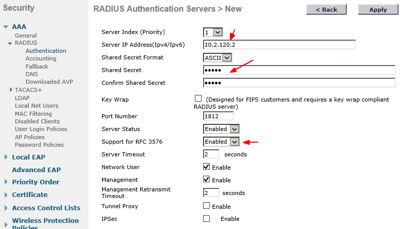
Go to Security -> AAA -> RADIUS -> Authentication and click New. Configure your RADIUS server IP and shared secret password. Check with your Server Admin to find out the RADIUS server parameters if you need to.
Under RADIUS Authentication Servers, change Auth Called Station ID Type to “IP Address”.
Configure the same IP address and Shared Secrete for Accounting Server. Leave all other fields default.
We may also prepare a guest user account for visitors. In the same Security tab, go to AAA ->TACACS+ -> Local Net Users. Here you can create guest users. Make sure to select the “visitor” from WLAN Profile.
The users created here are permanent. Accounts will not expire as opposed to the guest users created by Lobby Admin. Lobby Admin is explained in later session.
Create a SSID for Employees
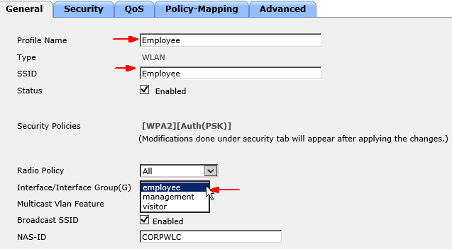
Go to WLANs -> WLANs and click on Create New. Name the SSID for employees. Make sure the correct Interface Group is selected. In this example, we select the “employee” interface from the pull-down menu.
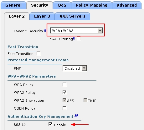
Setup Layer2 security using WPA and WPA2. You should never use WEP because of its obvious vulnerabilities. You do not need Layer 3 authentication because it is done at Layer 2 level.

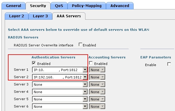
Enable RADIUS user authentication by selecting the RADIUS server(s) previously configured.
This is the basic configuration. You may keep everything else in default values.
Create a SSID for Visitors
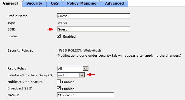
Mostly similar to creating the “Employee” SSID, do pay attention to these differences.
Create a SSID and assign to “visitor” Interface/Interface Groups.
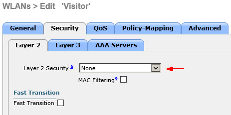
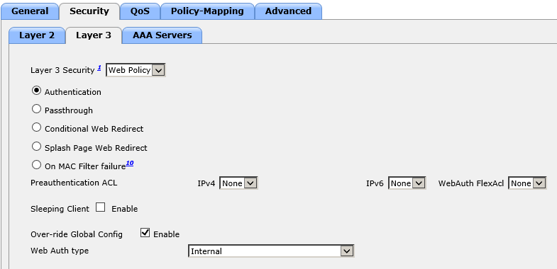
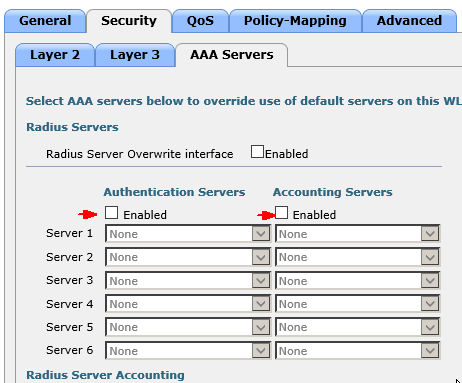
Select None for Layer 2 security and Web Policy/Authentication for Layer 3. Disable Authentication and Accounting servers in AAA.
Move up LOCAL in the Order Used For Authentication.
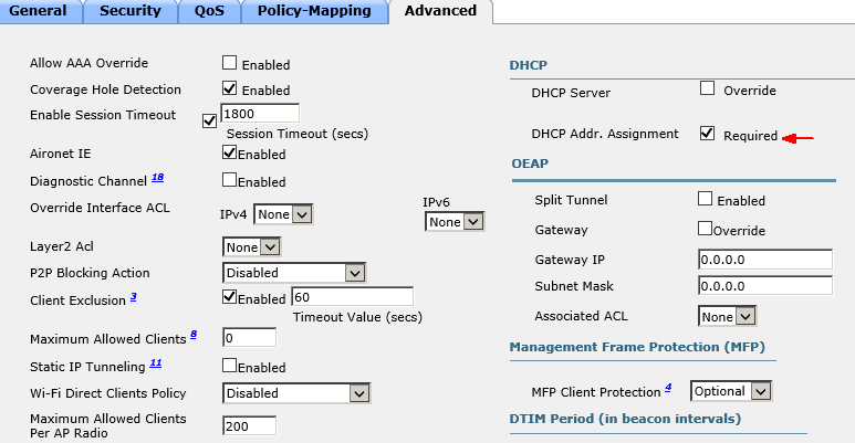
For security, we enforce the policy that guest users must obtain an IP from the Controller’s DHCP server to be able to connect. We do not allow static IPs on the guest network.
Apply the changes and now the SSID Guest is created.
Congratulations! Your wireless system is now up and running.
Basic Administration Guide
Create a Lobby Admin account and grant guest access as needed.
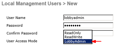
Go to Management -> Local Management Users. Here is where you can add admin to read-only account to access and configure the wireless Controller.
For example, you may create a Lobby Admin account that can only create guest users but does not have access to any configuration of the Controller. Here are the differences.
Read Write: full privilege admin
Reed Only: has access to see the configuration but cannot change anything
Lobby Admin: can only create guest user accounts. Has no access to see configurations.
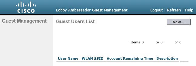
Here is how it looks when a Lobby Admin logs in. The only option for him/her is creating a new user account.
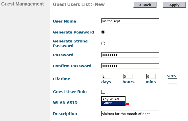
When creating a guest user account, make sure you select the Guest WLAN SSID instead of any. By default, guest account expires in a days.
Universal Wireless AP Provisioning and Priming (optional)
After you setup a Cisco controller based wireless system, everything seems to be working fine except the APs are still blinking blue, white and red. Check your AP’s model number if it has “UX” in the middle, you are running a Universal Wireless Access Point. You need to prime your APs to a specific country using AirProvision. As far as use of the AP if it is not primed, you will have limited capabilities:
- 5Ghz radios will not operate
- Clients are limited to 2.4ghz and 802.11g rates
- No 802.11n rates
- No 802.11ac rates
Follow my instruction on Cisco Universal Wireless AP Provisioning and Priming.
Equipment recommendations
Small to Medium-Sized Businesses
- Cisco 2500 Series Wireless Controllers, Virtual Wireless Controller, and the Cisco Catalyst 3650 Series Switch with integrated controller.
Medium and Large Single-Site Enterprises
- Cisco 5500 Series Wireless Controller
- Cisco Wireless Service Module 2 (WiSM2) Controller for Catalyst 6500 Series Switches
- Cisco Catalyst 3850 Series Switch with integrated controller
As one of the industry’s most deployed controllers, the 5500 Series Wireless Controller is designed for 802.11n performance, scalability, and optimal uptime. Roaming capabilities help ensure consistent experience on any smart mobile device with voice and video applications. Alternatively, deploy the Cisco Wireless Service Module 2 (WiSM2) Controller on the Catalyst 6500 Series Switches to help enable system wide wireless functions.
Multi-site Branch Wireless Deployments
- Centrally manage branch deployments with the Cisco Flex 7500 Series Wireless Controller. Its scalability lowers operating expenses by providing the visibility and control needed to manage thousands of wireless branches from a single location.
As far as industry trends are considered, wireless networks are certainly in high demand and growing at a phenomenal rate. The wireless technology is also expanding at an astounding rate.
Save some time and setup your wireless system in matter of minutes! You can download and import our working configuration described in this document. The package includes:
- INSTRUCTIONS.pdf – Read this instruction first It covers what each downloaded file is for and how to use them.
- Cisco Wireless Controller Configuration.pdf – The article in PDF format for your offline reference.
- AIR-CT2504-K9-8.1.111.0.cfg.txt – The working configuration for the Cisco Wireless System demonstrated here. You may use it on any compatible Cisco Wireless Controllers.
- Cisco-wireless-controller-x.png– Network diagram with IP addresses. Use it as reference while customizing the configuration to meet your needs.
As part of our documentation effort, we maintain current and accurate information we provided. Documentations are routinely reviewed and updated. We ask for your email address to keep you notified when the article is updated.
I’d love to hear from you!
If you have any questions regarding Cisco wireless controller configuration, feedback or suggestions for future topics, please leave a comment below.











Great content. It is exactly I was looking for. I followed your tutorial and set up our wireless system. Thank you!
Glad it helped.
how to ping from access point to other access point in wireless controller?
You can use the “Ping” tool from the upper right corner of the management GUI of the Controller. Or, you can ping a AP from CLI of the Controller. You cannot however initiate Ping from the Controller between APs.
thank you for your response. im newbie here. hope dont mind to teach me with my dumb question. if that cases, how to check the connectivity between each access point to each access point that connected with same wireless controller..
Please don’t hesitate to ask any questions. Keep in mind that all the APs are managed and monitored by the Controller once they joined the Controller. You can verify the AP’s status at Wireless –> All APs. If you don’t see them, they haven’t been provisioned properly. What you need to do is go back to session “Initial Setup for Wireless Access Points (WAP)” and follow the steps there. The easiest way to get it working is plug in the AP directly to the Controller and it’ll ensure to find the Controller at boot. Then you can put the AP at any where on your network, as long as the management traffic is routed, and the APs has reachability to the Controller, you are fine. Let me know how it goes with your setup.
I’m wondering how I can convert a lightweight AP to autonomous AP and vice versa.
Yo 00004000 u can use the controller GUI or CLI to configure up to ten QoS roles for guest users. If you choose to create an entry on the RADIUS server for a guest user and enable RADIUS authentication for the WLAN on which web authentication is performed rather than adding a guest user to the local user database from the controller, you need to assign the QoS role on the RADIUS server itself.
Thanks for your comment. That’s absolutely another good way to do it. The advantage of creating guest users on the controller itself is that you can delegate the role to the front desk or IT helpdesk. It is a quick and easy way to create, delete and set auto expiration of temp guest accounts on the web interface.
I will right away grab your rss as I can not find your e-mail subscription hyperlink or e-newsletter
service. Do you have any? Please let me realize in order that I could subscribe.
Thanks.
The email subscription is on the right side under categories and keyword tags. Thank you!