Businesses with multiple branch office locations often suffer connecting and sharing network resources over the WAN. They tend to think that the WAN technologies are very expensive and more for large enterprises with substantial capital. They didn’t realize that regardless your network size, small or large, the underlying design principles are mostly the same. More often, small businesses leverage cost efficient DSL, 4G LTE, and Internet over Coax cable to provide secondary or backup WAN connections. In this session, we will cover the basic WAN design for multiple office connectivity.
When we do WAN design, there’s a lot of similarities to how we do campus design. If we have a limited number of remote locations, let’s just say we have 500 to a thousand remote sites. We can do just a simple hub and spoke type topology where our main data center is the hub and all of our spokes simply connect directly to that. This can be scaled down all the way to just one HQ and one remote branch.
If we’ve got extremely large networks or they are geographically located, I’ve got maybe a US network, I have a European hub network, and maybe something Asia-Pacific, what I start to do is that I add distribution layers for the WAN in terms of regional aggregation sites per geography. We recommend using a datacenter as the hub site because you’ll need Uninterruptible Power Supply (UPS), cooling and high capacity internet pipes. Tier one and two Internet carriers tend to have presence at major datacenter and colocation facilities. The cost of a high bandwidth circuit is cheaper than what you can get at any office buildings.
WAN Design for Multiple Office Connectivity
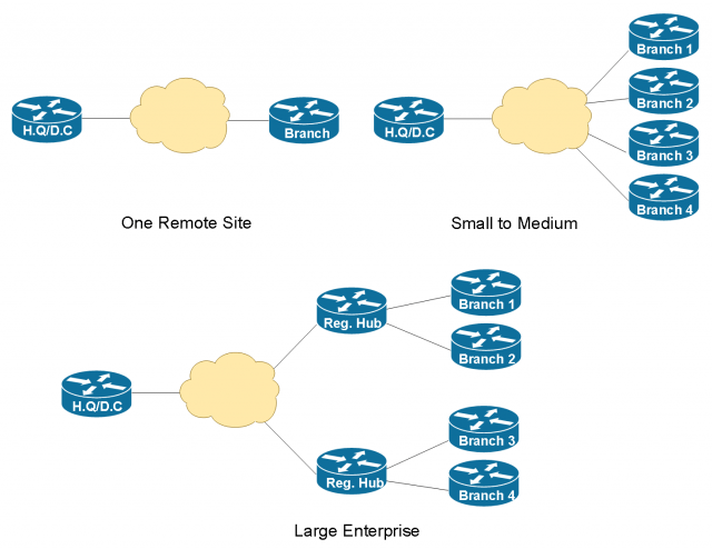
Remote Site WAN Designs
The design methodology for the remote site everything starts from this common basic building block of the single connected remote site- single router, single link. Everything builds based on this foundation. Everyone needs at least one router and one link for a remote site. If I need to add resiliency, one of way of doing that is take the single router and just add another link to it. So, we’ll start with the basic router and then we’ll give you a procedure to add the second link and adjust the routing.
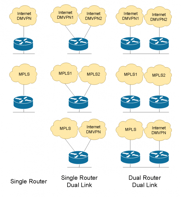
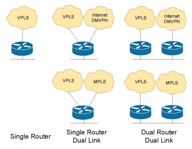
If I want additional resiliency in terms of hardware, now I add a second router, add a second WAN link on that router. On the LAN-facing side, I can do either HSRP or the routing on the LAN side to interconnect the devices. So, we always follow this design principle. I do the basic, I add a link or I add a router with another link. And these can be any different combinations. If you take a look at all the different ways we can do it, the non-redundant single link sites, we can add these single-router dual link sites, we can do dual links with dual routers and all the different transport combinations. Now, we’ve got eight different options here, and then we start adding layer2 links like VPLS or metro services, and 3G/4G. We treat 3G/4G the same way as any traditional physical Internet circuit. We build VPN transport on top of it.
On the LAN side, because a small site may have just a basic access layer, you connect a switch or use an embedded switch in the router module, and we may connect devices right there. That’s a flat access layer connected. We can do the same thing with dual router, and we probably would want to maybe do something with like a switch stack for resiliency and connect the routers to both stack members. We’ve got VLANs for voice and data. When we do dual router, we interconnect them with what we call a transit-net. It’s kind of a link that connects the two routers directly. So, if there’s traffic that needs to go between them, we don’t have to go out the data network.
Note that I’m not recommending any traditional static site-to-site VPN tunnels. Newer technology like DMVPN and iWAN allows building encrypted tunnels in a dynamic fashion without the dependency of underlying Internet transport type. The Internet service can be anything offered by the service provider, such as T-1, Metro Ethernet, DSL, 3G and 4G. One of the biggest advantages of DMVPN/iWAN technology is that you are no longer dependent on one service provider to providing IP transit and tunneling services. It used to involve tremendous pain when migrating from one service provider to another.
Remote Site LAN Designs
Let’s take a look at the LAN side. We’ve got recommendations on VLAN assignments and IP schemes and summarization. My general recommendation is as following:
- VLAN 10: Server Farm
- VLAN 11: User workstation Dada
- VLAN 12: User workstation VoIP
- VLAN 13: Wireless Data
- VLAN 14: Wireless VoIP
- …
- VLAN 99: Network transit or the “glue” network designed for router to router communications.
We always want to put VoIP traffic on its own VLAN and subnet for easy routing segmentation and applying QoS policies. Again, these are just the recommendations. VLAN numbers and names are arbitrary. You choose whatever makes sense for your network environment. The key here is that plan for the subnets while taking network summarization into consideration.
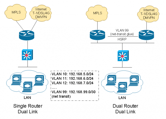
For example, we use /21s for all remote sites, so that would give us eight /24 networks to allocate. If you have less than eight remote sites, it makes perfect sense. If you need more or less IP subnetting, we could adjust it. Here I’m just giving you a model that you can start with and scale from there. When we start looking at bigger sites, maybe it’s not just the single building, it’s two buildings. I’ve got multiple access closets, now I need a distribution layer. Your remote site starts looking like a small campus. I’ll give you guides on how to connect to a distribution layer with either a single or a dual router model.
There are primarily three different ways that we could potentially connect our network distribution layer to the WAN Edge. So first of all, they’re all good. They all work and are all widely deployed.
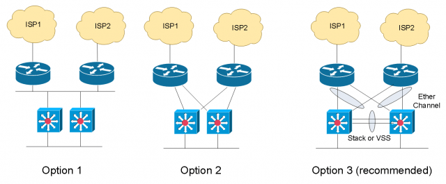
Among these three, option 3 is recommended. There are two reasons this is the recommended design. Number one of which is: because we use a virtual distribution layer, so either we have a switch stack or we have a VSS pair, or we have some highly-resilient modular switch that has multiple supervisors, we have a single control plane at the distribution layer. And then what we do is we use Multichassis EtherChannel and connect two physical links bundled in together for the interconnect from the distribution to the router. The benefit of doing so is that what we have is what looks to be a single logical link. Because of the way it simplifies the control plane and the management in terms of number of devices, and the resiliency it gives us in case we have a link failure.
The key thing to take away is that, at the distribution layer and the WAN Edge, you don’t want to do a lot of static routing (hopefully none). And you don’t want to use first-hop resiliency protocols like HSRP, VRRP, GLBP at the headquarters. We want to use dynamic routing protocols to dynamically learn subnets and network ranges at any location.
Sub-second failover at Core and Distribution layer
Let’s take a look at these two approaches of providing core and aggregation layer redundancy.
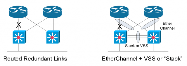
Here is just a quick comparison of what I call the routed link failover versus the EtherChannel failover approach. They’re both valid design methods, but the key difference is when we have a failure. If we’re using the routed point-to-point links and had a failure, the routing protocol has to figure out “what changed?”. So, at EIGRP, OSPF, they have to do some sort of recalculation or leverage a feasible successor and then they converge before traffic is flowing again. How long does it take? It depends on the routing protocol. It will be seconds to tens of seconds before the routing table re-converge. VoIP calls will definitely be dropped.
The later model on the right is where we have the virtual distribution layer when we use Multichassis EtherChannel and VSS at the core. When we have a link failure it is only a link within a port channel at layer two. We have a link that’s removed, but at layer three the topology has not changed. At layer three, everything is still the same.
We don’t have to do any route recalculation. All we’ve done is we’ve maybe gone from two one-gig links to a single one-gig link. So, we’ve lost some bandwidth and we have to maybe block all traffic for a short amount of time while we remove that channel member, but this failure is also going to be linear. It doesn’t matter how many prefixes you have in your route table since it’s only a layer two change. The routing didn’t have to change.
On the other hand, the example with the routed point-to-point links, the more prefixes you have in your route table the longer it’s going to take for the convergence to happen. It’ll still happen fast, but we want linearity and predictability, which is another thing we get from doing the Multichassis EtherChannel.
This was just a high level design overview of WAN design for multiple office connectivity. As you can see you have many options to design a low cost while highly redundant branch office WAN connection back to your HQ or datacenter. In the future sessions, we’ll dive into the details on how exactly we configure and manager the network.

Dear sir
i want to complete my project about wan design for multiple office connectivity so please help me advance for completion thanks
Hi Jack,
Regarding the Option 3 WAN edge design: shouldn’t two links between one WAN router and two VSS members be aggregated? The picture says links between one VSS member and two WAN routers are aggregated as if WAN routers provide mLAG and not VSS.
You are right. The picture is incorrect.